There are different types of capacitors available in the market. The key factor in distinguishing different types of capacitors is the dielectric used in its construction. Some of the common capacitor types are ceramic, electrolytic (which include Aluminium capacitors, Tantalum capacitors and Niobium capacitors), plastic film, paper and mica.
Each capacitor type has its own advantages and disadvantages. The characteristics and areas of applications may vary from one capacitor to other. Hence, when choosing a capacitor, following many factors must be considered.
Size: Both the physical dimension and the value of the capacitance is important.
Working Voltage: It is an important characteristic of the capacitor. It specifies the maximum voltage that can be applied across the capacitor.
Leakage Current: A small amount of current will flow through dielectric as they are not the perfect insulators. This is called leakage current.
Equivalent series resistance: The terminals of the capacitor have a small amount of resistance (usually less than 0.1Ω). This resistance becomes a problem when the capacitor used at high frequencies.
These factors determine how and in what applications a particular type of capacitor can be used. For example, the rated voltage of an electrolytic capacitor is larger when compared to a ceramic capacitor in the similar capacitance range.So they are generally used in power supply circuits. Similarly, some capacitors have very low leakage current and others have very high leakage current. Depending on the application, appropriate capacitor should be chosen.

Dielectrics in Capacitors
Fixed capacitors are more common types of capacitors. It is difficult to find an electronic circuit without a capacitor. Most of the capacitors are named after the dielectric used in the construction. Some of the common dielectrics used in the construction of capacitors are:
- Ceramic
- Paper
- Plastic film
- Mica
- Glass
- Aluminium Oxide
- Tantalum Pentoxide
- Niobium Pentoxide
The last three are used in electrolytic capacitors. Despite the use of different kinds of dielectrics in the construction of capacitors, the functionality of the capacitor doesn’t change: to store energy in the form of electric charge between the parallel plates.
Variable Capacitors
Like resistors, capacitors are also available as fixed and variable types. Variable capacitors are those in which the capacitance can be changed either mechanically or electronically. Such capacitors are generally used in resonant circuits (LC circuits) for tuning radios and impedance matching in antennas. These capacitors are usually called Tuning Capacitors.
There is another type of variable capacitors called Trimmer Capacitor. These are fixed on PCB’s and are used for the calibration of the equipment. They are non-polarised capacitors and are very small in size. They are generally not available for the use of regular customer. The capacitance of variable capacitors is very small which is usually in the order of few picofarads (generally less than 500pF).

Mechanical variable capacitors consist of a set of semi-circular metal plates fixed on the axis of a rotor. This setup is placed between a set of stator metal plates. The overall capacitance value (C) for this type of capacitors is determined according to the position of the moving metal plates with respect to the fixed metal plates. When the axis is turned, the area of overlap between the stator plates and rotor plates will vary and the capacitance is changed.
In this design, when the two sets of metal plates are fully meshed together , the capacitance value is generally at maximum value. High voltage type tuning capacitors have large air-gaps or spaces between the plates with relatively large break down voltages in order of kilo volts. For this reason these dielectric capacitors are very useful in tuning circuits.

Mechanical variable capacitors generally use air or plastic foils as dielectric. But the use of vacuum variable capacitors is increasing as they provide better working voltage range and higher current handling capabilities. The capacitance in the case of mechanically tuned capacitors can be varied using the screw on the top of the capacitor.
In the case of electronically controlled variable capacitors, a reverse biased diode is used in which the thickness of the depletion layer will vary according to the applied DC voltage. Such diodes are called Variable Capacitance Diodes or simply Varicaps or Varactors.
Ceramic Capacitors
Ceramic capacitors are the most used capacitors in the electronics industry. They are also the most produced capacitors with over 1000 billion units being produced every year. The name comes from the ceramic material which is the dielectric used in its construction.
Ceramic capacitors are fixed capacitance type capacitors and they are usually very small (in terms of both physical dimensions and capacitance). The capacitance of ceramic capacitors is usually in the range of picofarads to few micro farads (less than 10µF). They are non-polarised type capacitors and hence can be used in both DC as well as AC circuits.

The construction of these types of capacitors is very simple. A small ceramic disc is coated with silver on either side. Hence they are also called as Disc Capacitors. The ceramic acts as dielectric (insulator) and the silver coating will form the electrodes.
The thickness and the composition of the ceramic layer will determine the electrical properties of the capacitor. In order to achieve large capacitance values, multiple layers of such disc are stacked to form a multi-layer ceramic chip capacitor (MLCC). Modern electronics generally comprise of MLCC capacitors.
In order to achieve large capacitance, the dielectric constant of ceramic capacitors has to be very high. Ceramic capacitors are divided into two classes based on the areas of applications.
Class 1 Ceramic Capacitors
Often used in resonant circuits because of their high stability and low loss. The most common type of ceramic used in class 1 capacitor is made from Titanium dioxide (TiO2) with small portions of Zinc, Magnesium used as additional compounds. These are added in order to achieve the maximum possible linear characteristics.
Class 1 capacitors have low permitivity and hence the efficiency in terms of volume is relatively low. Therefore, the capacitance range of class 1 capacitors is low. The electrical losses of class 1 capacitors are very low and the dissipation factor is 0.15 percent. The value of the capacitance is independent of the applied voltage.
They have a liner temperature coefficient. All these characteristics of class 1 ceramic capacitors make them useful in the applications like filters with high Q factor and oscillator circuits like PLL’s. There is no fear of aging of class 1 ceramic capacitors.
Class 2 Ceramic Capacitors
Often used in buffers, coupling circuits and by-pass systems because of their high efficiency in terms of volume. This high volume efficiency is because of their high permittivity. The capacitance of class 2 capacitors will depend on the applied voltage and has a non-linear change for temperature changes.
The accuracy and stability are less when compared to class 1 ceramic capacitors. The ceramic for class 2 capacitors is made from ferro electric materials like Barium Titanate (BaTiO3) with additives like silicates of aluminium or magnesium and oxide of aluminium.
Because of the high permittivity in class 2 capacitors, high capacitance values are possible with smaller size than class 1 capacitors of same rated voltage. Hence, they are used in buffers, filters and coupling circuits where the capacitor is required to maintain a minimum capacitance. Class 2 capacitors can age over time.
Another class of ceramic capacitors is also available called Class 3 with higher permittivity and better volumetric efficiency. But the electrical characteristics of this class are worse along with poor accuracy and stability.
Generally, ceramic capacitors have less ESR (Equivalent series resistance) and leakage current when compared to electrolytic capacitors. The working voltage of class 1 ceramic capacitors is up to 1000V and that in class 2 ceramic capacitors is up to 2000V.
The main advantage of ceramic capacitors is that there are no coils inside its structure and so there is no inductance factor introduced during circuit operation. Hence, ceramic capacitors are suitable for high frequency applications.
Ceramic capacitors are available in normal two leaded through-hole structures, surface mount (SMT) multi layer mode and special lead less disc capacitors that are designed particularly for PCB’s. Both the through-hole and surface mount ceramic capacitors are frequently used. Ceramic capacitors are normally having a 3-digit number coded on their body to identify the capacitance value generally in picofarads (pF).
In that, the first two digits are used to indicate the capacitance value and the third digit indicates the number of zeros to be added. For example a ceramic capacitor with the markings 153 would indicate 15 and 3 zero’s in picofarads which is equivalent to15, 000 pF or 15nF.
Film Capacitor
Film capacitors are the most commonly used type of capacitors among all types of capacitors which have the difference in their dielectric properties. Film capacitors are the capacitors with an insulating plastic film as its dielectric and these are non-polarised capacitors.
The dielectric materials for these capacitors exist in the form of a thin layer which is provided with metallic electrodes and it is wounded into a cylindrical winding. Both electrodes of the film capacitors may be zinc or metalized aluminium.
The main advantage of film capacitor is direct connection between its internal construction and its electrodes on both ends of the winding. This direct contact with electrodes causes all current paths to become short.This design behaves like a large number of individual capacitors connected in parallel. And also this type of capacitors structure results in low ohmic losses and the low parasitic inductances . These film capacitors are used in AC power applications and also used in the high frequency applications.
Some of the examples of plastic films which are used as dielectric for the film capacitors are Polypropylene, Polyethylene naphthalate, Polyester, Polyphenylene sulfideand Polytetrafluoroethylene. Film type capacitors are in the market with capacitance value ranges from 5pF to 100uF .Film Film capacitors also available in different shapes and different styles which include,
- Wrap & Fill (Oval and Round) type: In this type the capacitor ends are sealed with epoxy and the capacitor is wrapped in a tight plastic tape.
- Epoxy Case (Rectangular & Round): In this type capacitors are encased in a moulded plastic shell and it is filled with epoxy.
- Metal Hermetically Sealed (Rectangular & Round): These types of capacitors are encased in a metal tube or can, and sealed with epoxy.
In present days the above all case style capacitors are available in both the types Radial and Axial Leads. The main advantage of the plastic film capacitors is that, they operate well and good at high temperatures when compared to other paper types.
These capacitors have small tolerance, high reliability and also they have very long service life. Examples of film type capacitors are cylindrical film, rectangular metalized film and foil film types. They are given below.

These capacitors have small tolerance, high reliability and also they have very long service life. Examples of film type capacitors are cylindrical film, rectangular metalized film and foil film types. They are given below.


Figure 4.Foil type film capacitors.
These film types of capacitors require much thicker dielectric material in order to avoid the punctures and tears in the dielectric film. Hence these are suited for low capacitance value and large sizes.
Film power capacitors
Film power capacitors are also called as Power film capacitors.The construction techniques and materials which are used for large power film capacitors are usually similar to those of the ordinary film capacitors. However these capacitors with high power ratings are used in the applications of power systems and electrical installations.

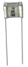
Polypropylene Capacitor
Polypropylene capacitor is one of the many varieties of film type capacitors. Polypropylene capacitors are the capacitors that have a polypropylene film as their dielectric. Polypropylene capacitors are available within the capacitance ranges from 100 pf to 10µF.
Polypropylene capacitors are also used in coupling and storage applications due to their high isolation resistance values. And also they have stable capacitance values for frequencies below 100KHZ. These polypropylene capacitors are used in the applications where we need to perform the tasks of noise suppression, coupling, filtering timing, blocking, bypassing, and handling pulses.

Polycarbonate capacitor
Polycarbonate capacitors are the capacitors that have a polycarbonate material as its dielectric. These types of capacitors are available within the capacitance range of 100pF to 10µF and have the working voltages up to 400V DC. These polycarbonate capacitors can operate with a temperature range of -55°C to +125°C without de-rating.
These capacitors have very good temperature coefficients, due to these reason polycarbonate capacitors are preferable. These capacitors are not used in the high-precision applications because of their high tolerance levels of 5% to 10%. The polycarbonate capacitors are also used for AC applications. Sometimes they are also found in switching power supplies.

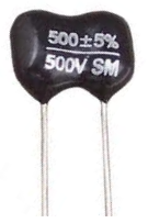
Silver Mica Capacitor
Silver Mica Capacitors are capacitors that are made from depositing a thin layer of silver on a mica material as its dielectric.The reason for the use of silver mica capacitors is their high performances compared to any other type of capacitors.
Silver mica capacitors can be obtained with the tolerance of +/- 1%. This is much better than any other type of capacitor which is available in today’s market. The temperature co-efficient of silver mica capacitors is much better than other types of capacitors.
And this value is positive and it is normally in the region of 35 to 75 ppm / C, with an average value of +50 ppm / C. Capacitance values for silver mica capacitors are normally in the range between a few pico-farads to 3300 pico -farads.Silver mica capacitors have very high levels of Q and also have small power factors. The silver mica capacitors have a voltage range between 100V to 1000 V.

Electrolytic Capacitors
Electrolytic Capacitors are generally used in the applications where very large capacitance values are required. The electrolytic capacitors have a metallic anode covered with an oxidized layer generally used as its dielectric. Another electrode of a capacitor is a non-solid or solid electrolyte.
Most of the electrolytic capacitors are polarized. These capacitors are categorized according to their dielectric material. Mainly these are categorized in to three classes, they are given as
- Aluminium electrolytic capacitors: Here aluminium acts as its dielectric.
- Tantalum electrolytic capacitors: Here tantalum pent oxide acts as its dielectric.
- Niobium electrolytic capacitors:Here niobium pent oxide acts as its dielectric
Usually the permittivity of tantalum pent oxide is almost three times greater than the permittivity of aluminum dioxide, but this permittivity determines only the dimensions. Generally three types of electrolytes are used.They are as follows:
- Non solid (wet or liquid): These capacitors have the conductivity nearly 10ms/cm and these are available with low cost.
- Solid manganese oxide: These capacitors have the conductivity nearly 100ms/cm and also have high quality and stability.
- Solid conductive polymer: These type of capacitors have conductivity approximately 10000 ms/cm and also the ESR values of <10m li="">
Electrolytic Capacitors are generally used in direct (DC) power supply circuits. These are also used in the applications of coupling and decoupling to reduce ripple voltage, due to their large capacitance values and their small size. One of the main disadvantages of electrolytic capacitors is their low voltage ratings.
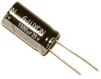
Aluminum Electrolytic Capacitors
Aluminum Capacitors are capacitors that are made of oxide film on aluminum foils with a strip of absorbent paper between them which is soaked in an electrolyte solution and all these design can be sealed in a can. Basically there are two types of Aluminum Electrolytic Capacitors they are plain foil type and etched foil type.
Plain foil type electrolytic capacitors are mainly used as smoothing capacitors in power supply circuits while etched foil type capacitors are used in coupling DC blocking and by pass circuits.
Electrolytic aluminum capacitors cover the capacitance range of 1uF to 47000uF and large tolerance of 20%. The working voltage ratings range up to 500V. These are cheaper and easily available in the market.
The capacitance value and voltage ratings are either printed in uF’s or coded by a letter followed by three digits. These three digits represent the capacitance value in pF where first two digits represent the number and the third one is the multiplier digit.

Tantalum Electrolytic Capacitors
Tantalum Capacitors are capacitors that are made of tantalum pentoxide as its dielectric material. Tantalum electrolytic capacitors are also polarised capacitors like aluminum capacitors.Tantalum electrolytic capacitors are obtained in both the types of wet (foil) and dry (solid).
The second terminal of tantalum electrolytic capacitors is smaller than the terminal of equivalent aluminum capacitors and that terminal is made with manganese dioxide.
The main advantage of Tantalum Electrolytic Capacitorsover aluminum capacitors is that they are more stable, lighter and smaller. They have capacitance values range from 47nF to 470uF and maximum working voltage up to 50V. These are costlier than aluminum electrolytes.
The properties of the tantalum oxide dielectric are low leakage current and better capacitance stability. These properties of tantalum oxide dielectric make them suitable to be used in blocking, by-passing, decoupling, filtering and timing applications. And also these properties are much better than the dielectric of aluminum oxide.

Super-capacitors
The super- capacitor is also known as ultra-capacitor or electric double-layer capacitor. These capacitors are made with a thin electrolyte separator which is flanked with activated carbon ions. It differs from a regular capacitor,the capacitance value of a super capacitor is very high and it is in order of milli farads with the voltage ranges of 2.3V to 2.75V.
Super capacitors are categorized into three types based on their electrode design they are
- Double-layer capacitors: These capacitors have carbon electrodes or their derivatives.
- Pseudo capacitors: These capacitors have metal oxide or conducting polymer electrodes.
- Hybrid capacitors: These capacitors have asymmetric electrodes.
Super capacitors are mainly used in the applications, where very high number of charge/discharge cycles is needed, where long lifetime is required and where the large amount of power is needed within a short time.The typical applications range of super capacitors are from milliamp current and milli-watts of power with a duration of few minutes to several amps current and several kilo watts power within a shorter period. These super capacitors are generally used as temporary power source, as a replacement of batteries.


