When equal values of direct voltage and alternating voltage are applied to the same circuit which has inductor in series with the load, more current would flow in a DC circuit than in an AC circuit.
This is because, only induced voltage opposes the current flow in DC circuit when the current approaches to its maximum value and once it reaches to a steady state value, there will be no more inductive effect.
In the case of AC circuits, current is continuously changing, therefore inductive effect is present at all time. Consider the following DC and AC circuits to understand this concept.
DC Inductive Circuit

In the above figure, if the switch is operated from node A to node B and immediately from node B to node A, a change in current flows through the circuit.
This change in current induces an emf in the inductor proportional to the rate of change of current and this emf opposes the applied voltage (which is the cause for the production of current). This is called self induction.
Once the current reaches a steady state value, there will be no self induction in the inductor and hence no opposition to the current flow.
AC Inductive Circuit

We know that, when AC current is applied to the circuit, current continuously changes at a supply frequency rate and hence the back emf will change accordingly.
This back emf opposes the supply voltage and hence the flow of current is limited. Therefore, the actual opposition to the current flow created by an inductor in an AC circuit is referred as the inductive reactance.
Inductive reactance in an Inductor
In an inductive circuit by observing the self-inductance and its effect within the circuit, we can define the inductive reactance. The magnetic field induces the voltage in the inductor which is always opposite in polarity to the voltage that produces it, i.e., applied voltage.
This opposing voltage limits the current flowing through an inductor and it is called reactance (X). Since this reactance is caused due to inductance, it is called inductive reactance (XL). It is measured in Ohms.

The amount of inductive reactance offered by an inductor is proportional to the inductance and frequency of applied voltage. This reactance can be determined by the following formula.
XL = 2 π fL
Where XL= inductive reactance in ohms
π = 3.14
f = frequency in Hertz (Hz)
L = inductance in Henrys (H)
According to the ohm’s law, inductive reactance is directly proportional to the applied voltage and inversely proportional to the current. It can be expressed as
I = V/XL
From the above equation it is clear that increasing voltage or decreasing inductive reactance causes an increase in current. Likewise, current decreases with increase in inductive reactance and decrease in voltage.
Any practical inductor must be made with wound wire which consists of some resistance so it is not possible to obtain a purely inductive coil.
Therefore, there are two factors that oppose the current flow in an inductor, namely resistance associated with the coil (which is considered as separate resistor R in series with inductor) and inductive reactance offered by the inductance property.
Thus the total current limiting property of an inductor in AC circuit is the combination of resistance and reactance which is called the impedance, Z.


Thus, the current and voltage not exactly maintains 900 phase shift, but less than that of purely inductive case as shown below.


This impedance value is calculated by Ohm’s law and is given as
Z = V / I
Where Z = total opposition offered by inductor to the current flow, in ohms
V = applied voltage
I = current flowing through the circuit
Impedance Triangle
Another method of determining the impedance is the use of impedance triangle method when inductive reactance and resistance values are known. Below diagram shows an impedance triangle which consists of resistance and reactance vectors.

In the above figure, resistance vector is along with horizontal line (because resistance does not offer any phase shift) and inductive reactance vector is along with vertical line (because pure inductance offers 900 phase shift).
By connecting the ends of these two vectors, impedance, Z is obtained. Therefore, the total opposition to current or impedance can be calculated by
Z = √[(R)2+(XL)2 ]
Where
Z = impedance in ohms
R = resistance in ohms
XL = inductive reactance in ohms
Also, from above diagram,
tan∅= XL/R
sin∅= XL/R
cos∅= R/Z
RL Circuits and Inductive Reactance
The figure below shows the relationship between applied voltage and current through an inductive circuit. In a pure inductive circuit, the current lags the source voltage by 900 . It can also be stated as source voltage leads the current by 900 in an inductive circuit.

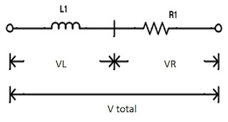
When an inductor is connected in series with the resistor RL, series circuit is obtained as shown below. This can also be considered as inductance consisting of some resistance


The figure below shows the vector diagram of RL series circuit consisting of voltage drop vectors across resistor and inductor. AE represents the current reference line. AB represents the voltage drop across the resistance which is in phase with current line.
AD represents the inductive voltage drop which leads the current by 900. The resultant of these vectors gives the total voltage across the circuit.

By applying the Pythagoras’s theorem to above voltage triangle, we get
Vtotal= √(VL2+VR2)
tan∅= VL/VR
We know that VR=I×R and VL=I×XL
By these equations we can rewrite the Vtotal as
Vtotal= √((I×R)2+(I×XL)2 )
I = V/ √((R)2+(XL)2) = V/Z (Amps)
No comments:
Post a Comment